- No products in the cart.


A key design consideration for making connections to an IC is the diameter of the bonding wire, which involves a trade-off between mechanical properties, electrical properties, and cost.
The diameter of wires used for wire bonding can be specified using three different units: microns (μm, or 0.001 mm), mils (1 mil = 0.001 inch), or AWG. The conversion of mils to microns is 1 mil = 25.4 microns; a helpful table to convert AWG to mil and micron units can be found at https://www.rapidtables.com/calc/wire/wire-gauge-chart.html. The most common wire bonding diameters used are 25.4 μm and 17.8 μm (1 mil and 0.7 mil), but wires between 5 and 500 are commercially available [1].
1. Mechanical Properties - elongation and breaking load as a function of bonding wire gauge
The most important mechanical parameters of a bonding wire are the amount its length can be increased before it permanently deforms (the elongation), and the amount of load it can support before breaking (the breaking load). The method that should be used for measurement of these parameters for bonding wire is described in detail in ASTM method F72.
For gold bonding wire, both of these properties improve with increasing diameter. For example, when increasing the wire diameter from 0.7 to 2 mils, the elongation increases from 2-5% to 4-12%, and breaking load increases from 3-9 cN to 28-64 cN, depending on alloying [2] (1 cN = 0.01 N).
2. Length
The rule of thumb for wire length is to restrict it to less than roughly 100X the wire diameter [3].

3. Current-carrying capacity and its relationship to bonding wire gauge
During operation, the bonding wire will heat up due to current flow, and excessive heating can lead to wire burnout. The amount of heating is proportional to the current density, or current divided by the cross-sectional area of the wire (A/mil2 or A/μm2, for example). For this reason, the wire diameter sets a maximum current. For 1 mil gold wire, the maximum current capacity is roughly 0.7 A. However, because the wire cools through conduction and convection to balance the heating from current flow, the maximum current varies based on wire length and degree of cooling also, so this figure can vary significantly based on other design parameters.
4. Resistance
The electrical resistance of any wire (in Ω) is proportional to the electrical resistivity of the wire material, the wire’s cross-sectional area, and its length. The formula to calculate electrical resistance of a bonding wire is:
R = ρ × L / A
where R is the resistance (in Ω), ρ is the material resistance (in units of Ω times length), A is the cross-sectional area of the wire, and L is the wire length. The resistance of 1 mil gold bonding wire is about 0.05 Ω per mm length.
5. Bond pad size and pitch
The bond pad pitch, or distance between bond pads, determines the maximum bond pad size. The bond pad size, in turn, limits the bonding wire diameter that can be used. The size of the bond pad can be specified using the minimum circle diameter that can be enclosed inside the bond pad. This circle is typically approximately 3-4X the wire diameter for ball bonds, and ~ 2.5-3X the wire diameter for wedge bonds for 1 and 0.7 mil wire [3, 4,5].
Additional, more detailed guidelines for bond pad design and wire placement can be found in Ref. 6.
6. Cost
For gold bonding wire, the majority of the cost is in the actual material, rather than processing cost. Therefore, the cost per unit length can be simply estimated as proportional to the cross-sectional wire area. By decreasing the wire diameter from 2 to 1 mil, for example, the cost can be reduced by approximately 4X.
Other bonding wire specifications related to bonding wire gauge
There are a number of ASTM and MIL methods/specifications that cover the quality of bonding wire, and the quality of wire bonds themselves. These include:
-
ASTM 72, “Standard Specification for Gold Wire for Semiconductor Lead Bonding” - a comprehensive spec for gold bonding wire, including wire mechanical properties, chemical composition (important for alloyed wire materials), visual appearance, and shape.
-
ASTM F205, “Test Method for Measuring Diameter of Fine Wire by Weighing”
-
ASTM F219, “Test Methods of Testing Fine Round and Flat Wire for Electron Devices and Lamps”
-
ASTM F458, “Standard Practice for Nondestructive Pull Testing of Wire Bonds”
-
ASTM F459, “Standard Test Methods for Measuring Pull Strength of Microelectronic Wire Bonds”
-
ASTM F584, “Practice for Visual Inspection of Semiconductor Lead-Bonding Wire”
-
ASTM F1269, “Standard Test Methods for Destructive Shear Testing of Ball Bonds”
-
MIL-STD-883 - this is another comprehensive method that is generally applied to determine the suitability of microelectronic circuits for military applications, and includes specific testing of wire bonds, including destructive and nondestructive pull tests on wire bonds, and visual inspection of the bonds and the bonding wire.

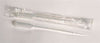
Excelta Cutting Tweezer 15A-RW
Tools for handling and cutting bonding wire
Proper, safe handling of bonding wire is essential for high-quality, reliable wire bonds. Furthermore, specialized tools are usually required to reach and work in the confined spaces found in IC interconnect structures. For this reason, specially designed and selected precision cutting tweezers are recommended for handling and cutting bonding wire. Cutting tweezers, in particular, should be selected based on hardness and ability to cut the material and gauge of wire being used, and geometry of the interconnects.
The cutting surfaces of cutting tweezers should be cleaned and inspected regularly for wear and damage.
There are a number of considerations when selecting a bonding wire diameter, which are mainly related to cost, desired electrical properties, and matching to a particular die geometry. ASTM and MIL specs can be very helpful to ensure that the latter two factors are fully accounted for.
For over 40 years, Lab Pro has been committed to delivering the highest quality cutters and tweezers to tech laboratories worldwide. Come visit the biggest Lab Supply showroom in California, or contact us online or at 888-452-2776.
References
-
Charles Jr, H. (2001) Microelectronic Packaging: Electrical Interconnections, in Encyclopedia of Materials: Science and Technology (Second Edition).
-
https://www.ece.ubc.ca/~robertor/Links_files/Files/MaxtekWireBondingArticle0706.pdf
-
Schuettler, M., & Stieglitz, T. (2013). Microassembly and micropackaging of implantable systems. In Implantable Sensor Systems for Medical Applications (pp. 108-149). Woodhead Publishing.